- 您现在的位置:买卖IC网 > Sheet目录381 > 4272-00 (Peregrine Semiconductor)KIT EVAL FOR 4272 RF SWITCH
PE4272
Product Specification
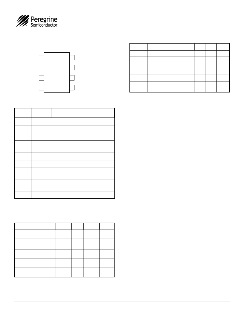
Figure 3. Pin Configuration (Top View)
Table 4. Absolute Maximum Ratings
Symbol
V DD
Parameter/Conditions
Power supply voltage
Min
-0.3
Max
4.0
Units
V
V DD
1
8
RF1
V I
Voltage on any input
-0.3
V DD +
0.3
V
CTRL
GND
RFC
2
3
4
4272
7
6
5
GND
GND
RF2
T ST
P IN
V ESD
Storage temperature range
Input power (50 ? )
ESD voltage (HBM, ML_STD
883 Method 3015.7)
-65
150
34
1500
°C
dBm
V
Absolute Maximum Ratings are those values
Table 2. Pin Descriptions
listed in the above table. Exceeding these values
Pin
No.
1
2
3
4
5
6
7
8
Pin
Name
V DD
CTRL
GND
RFC
RF2
GND
GND
RF1
Description
Nominal +3 V supply connection.
CMOS logic level:
High = RFC to RF1 signal path
Low = RFC to RF2 signal path
Ground connection. Traces should be
physically short and connected to ground
plane for best performance.
RF Common port. 4
RF2 port. 4
Ground Connection. Traces should be
physically short and connected to ground
plane for best performance.
Ground Connection. Traces should be
physically short and connected to ground
plane for best performance.
RF1 port. 4
may cause permanent device damage.
Functional operation should be restricted to the
limits in the Operating Ranges table. Exposure to
absolute maximum ratings for extended periods
may affect device reliability.
Latch-Up Avoidance
Unlike conventional CMOS devices, UltraCMOS?
devices are immune to latch-up.
Electrostatic Discharge (ESD) Precautions
When handling this UltraCMOS? device, observe
the same precautions that you would use with
other ESD-sensitive devices. Although this device
contains circuitry to protect it from damage due to
ESD, precautions should be taken to avoid
exceeding the rating specified in Table 4.
Note:
4. All RF pins must be DC blocked with an external
series capacitor or held at 0 V DC .
Table 3. Operating Ranges
Parameter
V DD Power Supply Voltage
Min
2.7
Typ
3.0
Max
3.3
Units
V
I DD Power Supply Current
(V DD = 3 V, CTRL = 3 V)
Operating temperature
range
-40
8
20
85
μ A
°C
Control Voltage High
Control Voltage Low
0.7xV DD
0.3xV DD
V
V
?2005 Peregrine Semiconductor Corp. All rights reserved.
Document No. 70-0173-03 │ UltraCMOS? RFIC Solutions
Page 2 of 11
Peregrine products are protected under one or more of the following U.S. Patents: http://patents.psemi.com
发布紧急采购,3分钟左右您将得到回复。
相关PDF资料
4273-00
KIT EVAL FOR 4273 RF SWITCH
42742-03
KIT EVAL FOR 42742 RF SWITCH
4280-52
IC RF SWITCH SPDT 75 OHM 20QFN
4283-00
KIT EVAL FOR 4283 RF SWITCH
4302-00
KIT EVAL FOR 4302 RF DSA
4304-00
KIT EVAL FOR PE4304 RF DSA
4305-00
KIT EVAL FOR 4305 RF DSA
4306-00
KIT EVAL FOR 4306 RF DSA
相关代理商/技术参数
4272-01
制造商:PEREGRINE 制造商全称:PEREGRINE 功能描述:SPDT Broadband UltraCMOS? DC - 3 GHz RF Switch
4272-02
制造商:PEREGRINE 制造商全称:PEREGRINE 功能描述:SPDT Broadband UltraCMOS? DC - 3 GHz RF Switch
427204
功能描述:环形推拉式连接器 Panel Mnt Recpt 14-Pole #26 PCB
RoHS:否 制造商:Hirose Connector 产品类型:Connectors 系列:HR10 触点类型:Socket (Female) 外壳类型:Receptacle 触点数量:4 外壳大小:7 安装风格:Panel 端接类型:Solder 电流额定值:2 A
427208
功能描述:环形推拉式连接器 Panel Mnt Recpt 10- Pole #26 solder cup
RoHS:否 制造商:Hirose Connector 产品类型:Connectors 系列:HR10 触点类型:Socket (Female) 外壳类型:Receptacle 触点数量:4 外壳大小:7 安装风格:Panel 端接类型:Solder 电流额定值:2 A
42721-1
功能描述:端子 RING IS 20-16 .132 .0253BR
RoHS:否 制造商:AVX 产品:Junction Box - Wire to Wire 系列:9826 线规:26-18 接线柱/接头大小: 绝缘: 颜色:Red 型式:Female 触点电镀:Tin over Nickel 触点材料:Beryllium Copper, Phosphor Bronze 端接类型:Crimp
427212
功能描述:环形推拉式连接器 Panel Mnt Recpt 14- Pole #26 solder cup
RoHS:否 制造商:Hirose Connector 产品类型:Connectors 系列:HR10 触点类型:Socket (Female) 外壳类型:Receptacle 触点数量:4 外壳大小:7 安装风格:Panel 端接类型:Solder 电流额定值:2 A
42721-2
制造商:TE Connectivity 功能描述:RING IS 20-16 .132 .0253TPBR - Bulk
4272-15P
功能描述:D-Sub工具与硬件 CIR CONN COVER 15P
RoHS:否 制造商:3M Electronic Solutions Division 产品:Accessories 类型:Strain Relief, 36 Position 用于:Wiremount D-Sub Connectors
